Introduction
This document describes the electrical characteristics of the Hummingbird Duo Controller and Duo kit parts.
Table of Contents
1. Hummingbird Duo Controller

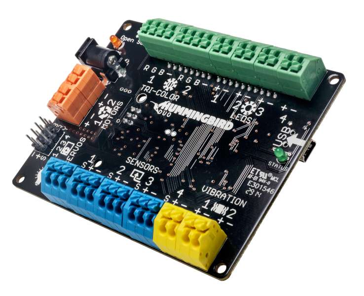
The Hummingbird Duo controller board interfaces the kit motors, LEDs, and sensors with a computer. It is possible to interface non-kit components to Hummingbird, but one must be careful to observe the limits specified in the following sections.
1.1 Power
Hummingbird Duo can receive power from two sources: a USB port provides power to the microcontroller, LEDs, vibration motors, and sensors. The Motor Power barrel jack connector connects the included power supply to provide power to the motors and servos. If USB is unplugged, this port can power the entire controller.
| Characteristic | Value |
| USB supply voltage | 5 V |
| USB maximum current | 500 mA |
| Auxiliary supply input voltage | 100-240 VAC |
| Auxiliary supply output voltage | 5 V |
| Auxiliary supply maximum current | 2000 mA |
If you wish to use your own power supply to power the Hummingbird, connect it to the Motor Power port. The supply must be between 5V and 8V for the Duo controller to operate normally. Exceeding 8V may damage attached kit servos and motors, exceeding 10V will damage the Hummingbird controller.
1.2 Microcontrollers
Hummingbird uses an Atmel Atmega32U4 microcontroller as its main processor, and also includes an ATtiny24A to control gear motors and hobby servos. Hummingbird comes preloaded with default firmware that allows it to work in USB-tethered mode with Snap!, Python, or Java. A bootloader allows the main firmware to be overwritten via USB (for instance, to load an Arduino program on the Hummingbird). It is possible to modify the bootloader or the ATtiny24A firmware by populating the ISP header and using an AVRISP tool to download new firmware.
1.3 LED Ports
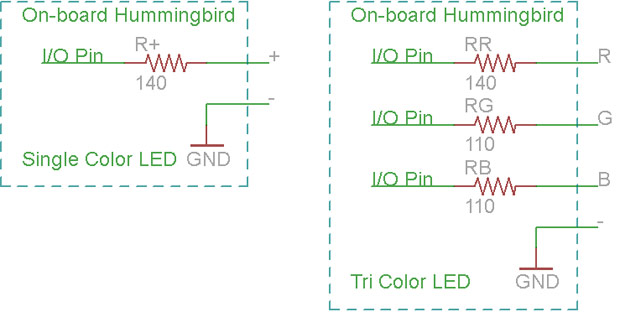
Hummingbird has four single color LEDs ports, and two tri-color LED ports. As the ports are designed to power LEDs, the board has built-in resistors to limit current to the LED elements. The resistor values are 140 Ohm for single color LEDs and the R terminal of the tri-color LED, and 110 Ohm for the G and B terminals of the tri-color LED. The resistors are sized to drive 20mA through each LED or each color element of a tri-color LED. The following schematics describe the on-board circuitry of the single and tri-color LED ports:

1.4 Vibration Motor Ports
The two vibration motor ports are controlled using an FDS9926A dual MOSFET driver. A PWM signal from the microcontroller to the gate of the MOSFET allows speed control of the motor. The vibration motors are powered from the Hummingbird’s 3.3V regulator, which is capable of no more than 300 mA total. Each vibration motor consumes roughly 75mA.
1.5 Sensor Ports
The Hummingbird’s four sensor ports each have terminals for sensor power (Regulated to +5 volts), sensor ground, and an analog sensor signal. Each sensor signal is read with up to 10-bit resolution over the range of 0 to 5.0 V. To avoid damage, the sensor signal should stay between -0.7V and 5.7V at all times.
1.6 Motor Ports
The Hummingbird’s two motor ports are designed to drive small DC motors. Hummingbird uses an A3909 dual H-bridge to control these motors The maximum current draw from each motor port is 1 Amp. The motors are driven at the voltage of the auxiliary power supply.
1.7 Servo Ports
Hummingbird’s four servo ports are designed for compatability with standard RC servos. The servo signals pulse every 20ms and have a programmable up-time between 0.6 and 2.4ms. The servos share the auxiliary power supply with the motor ports, and the total current draw combined for all motors and servos should not exceed 2000 mA.
1.8 Schematic and Design Files
You can view the Hummingbird Duo schematic and layout at our Github repository.
2. LEDs
Hummingbird Duo kits include single color LEDs and tri-color LEDs. The tri-color LEDs are common cathode style.
Single Color LED Characteristics
| Characteristic | Red/Yellow/Orange | Green |
| Forward voltage | 1.7 V | 2.3 V |
| Recommended current | 20 mA | 20 mA |
| Light output (Lumens) | 6,000-10,000 | 10,000 |
Tri-Color LED Characteristics
| Characteristic | Red | Green | Blue |
| Forward voltage | 2.0 V | 3.3 V | 3.3 V |
| Recommended current | 20 mA | 20 mA | 20 mA |
| Light out (Lumens) | 10,000 | 10,000 | 5,000 |
3. Vibration Motors
Hummingbird Premium and classroom kits include vibration motors.
| Characteristic | Value |
| Operating Voltage | 2.4-3.6V |
| Free-run speed @3V | 2500 RPM |
| Free-run current@3V | 70 mA |
| Stall current@3V | 80 mA |
4. Gear Motors
The Hummingbird Duo premium and classroom kits include gear motors. Mounting a wheel or other item to the shaft of the gear motor requires #2 1/4″ sheet metal screws. These are included with the wheels and adaptors in the premium and classroom kits.
| Characteristic | Value |
| Operating Voltage | 3-6V |
| Free-run speed @6V | 45 RPM |
| Free-run current@6V | 70 mA |
| Stall current@6V | 800 mA |
| Stall torque@6V | 100 oz-in |
| Weight | 33g |
| Gear ratio | 228:1 |
5. Servos
The Hummingbird Duo comes with Hitec HS-311 servos as well as servo extension cables.
| Characteristic | Value |
| Operating Voltage | 4.8-7.2V |
| Rotational range | 180 degrees |
| Speed @4.8V | 0.19 seconds per 60 degrees travel |
| Idle current @4.8V | 7.4 mA |
| No load current@4.8V | 160 mA |
| Stall current@4.8V | 700 mA |
| Stall torque@4.8V | 42 oz-in |
| Weight | 43g |
6. Sensors
The Hummingbird kit contains five sensors; each sensor produces an analog voltage based on the characteristic it is sensing.
6.1 Light Sensor
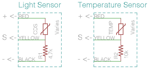
The light sensor detects the intensity of light shining on the surface of the sensor. Higher values correspond to more light. The sensor is based on a PDV-P9002 photoconductive cell. This cell changes its resistance based on light level; to transform the change in resistance to a change in voltage the cell is placed in series with a regular 4.7KOhm resistor. See the following schematics for circuits of the light and temperature sensors:

6.2 Temperature Sensor
The temperature sensor reports the ambient temperature of the black probe at the tip of the sensor. The sensor requires contact with an object in order to report an accurate temperature. A temperature reading can take up 10 seconds to stabilize to the temperature of the object in contact with the probe. The sensor is based on an MF52 NTC thermistor, which varies its resistance with temperature. A 10 KOhm resistor in series with the thermistor completes the sensor circuit.
6.3 Distance Sensor
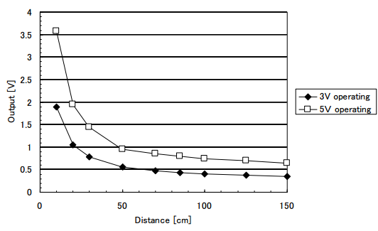
The Hummingbird Duo distance sensor is based on the Sharp GP2Y0A60SZ0F module. The sensor can work with either a voltage between 2.7V to 3.6V or one between 4.5 to 5.5V to operate, and draws 33mA. The sensor circuit board is configured to work with 4.5V to 5.5V by default. To switch the voltage range, desolder resistor located under the connector. The sensor circuit board has a protection diode to prevent the sensor module from being damaged in the event that it is connected to the Hummingbird incorrectly.
In our tests, the sensor can reliably detect objects from 5 to 100 centimeters away (although it is advertised to work from 10 to 150cm). The output is not linear with distance; see the following graph to match the sensor’s value with distance:

6.4 Sound Sensor
The sound sensor outputs 0.2 volts until a threshold sound level is reached; above this level it will respond with an increasing voltage to increasingly loud sounds, saturating at around 1.5V. The sensor requires between 3.6V and 5.5V to operate, and draws roughly 5mA. The sensor circuit board contains a protection diode to prevent sensor failure in case the sensor is connected to the Hummingbird incorrectly.
6.5 Knob
The knob used in the Hummingbird is a 10 KOhm rotary potentiometer >with a separate knob. An additional 100 Ohm resistor is soldered to the yellow signal wire of the connector to protect the sensor and Hummingbird in the event that the sensor is incorrectly connected to the Hummingbird.