Register to receive free access to all teacher materials.

l Projects
Programming Language
Any language supported by Hummingbird Duo
Free Teacher Materials
Objective & Learning Goals
Student will learn to use the Hummingbird Joystick to create a game.
Standards
COMPUTER SCIENCE TEACHERS’ ASSOCIATION (CSTA)
CSTA Standards are split into different grade levels: 3-5, 6-8, and 9-10. Working with the Hummingbird Robotics Kit meets multiple standards across these grade-level delegations.
Visit this page for a more detailed explanation of how working with the Hummingbird Robotics Kit applies to meeting CSTA Standards.
Photo Gallery
Sensors enable you to create a robot that interacts with people or its environment. You can make robots that respond to light, sound, etc. To expand your creative options even further, there is now a joystick that you can use with the Hummingbird. You can use it to create your own games or control a robot!
Connecting to the Joystick
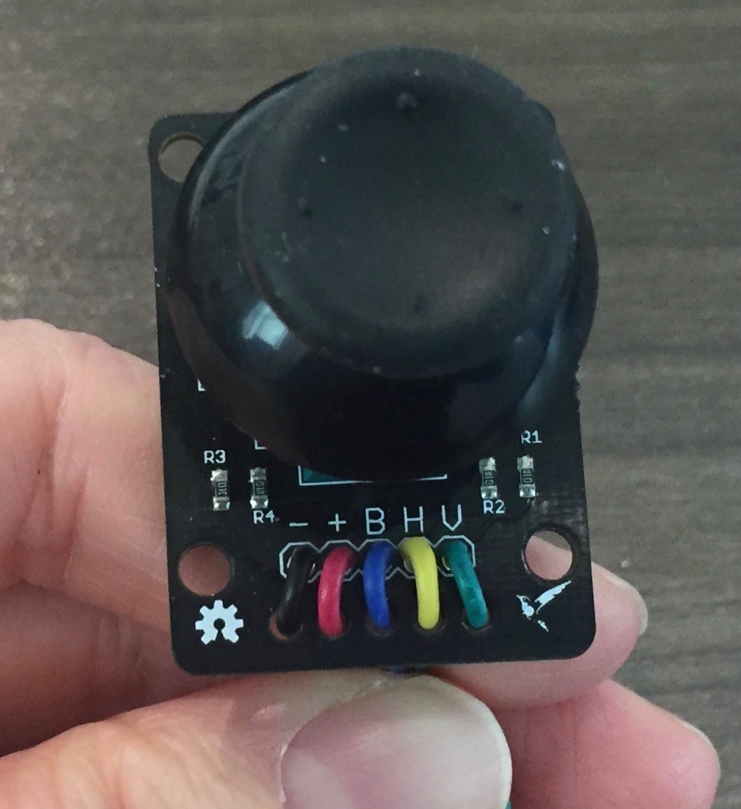
The joystick is a combination of three sensors. First, the entire joystick can be pressed as button. This wire carrying this information is blue and labelled ‘B’ on the joystick board. Another sensor measures horizontal movement of the joystick (H: yellow wire), and the third sensor measures vertical movement of the joystick (V: green wire). The joystick also has wires for power (+: red wire) and ground (-: black wire).
Connecting the joystick to the Hummingbird requires three sensor ports. Power (+) and ground (-) should be connected to the ‘+’ and ‘-’ terminals of one sensor port. In the picture below, they are connected to sensor port 1. The other three wires from the joystick should be connected to the ‘S’ terminals of three different sensor ports. In the picture below, the button is connected to sensor port 1, the horizontal sensor to sensor port 2, and the vertical sensor to sensor port 3.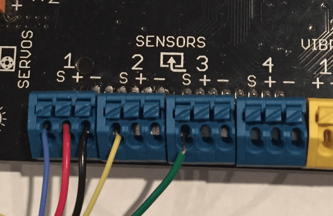
Controlling a Sprite in Scratch
To find the value of each of the joystick sensors in Scratch, you can use the HB voltage block at the bottom of the More Blocks menu. Remember to select the correct sensor port for the button, the horizontal sensor, or the vertical sensor.
The voltage for each sensor varies between 0 and 5 V. The voltage for the button is close to 5 V when the button is pressed, and close to 0 V otherwise. The script below uses a threshold of 2.5 V to determine whether or not the button is being pressed. When it is, the sprite on the screen says, “Button pressed.”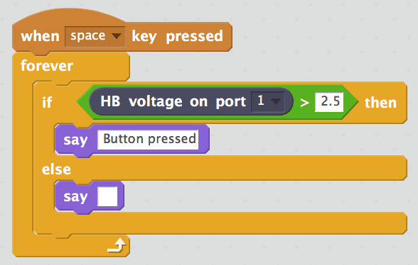
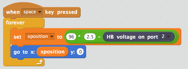
The joystick can be used to move a sprite in Scratch to make a game. The horizontal and vertical position of the joystick can control the horizontal and vertical position of the sprite on the screen, respectively. To control the horizontal position of the sprite, the 0 to 5 V range of the horizontal sensor must be converted to the -240 to 240 range of the stage x-axis.
First, we subtract the value of the horizontal sensor from 2.5. The range for this block is -2.5 to 2.5.
Next, we multiply the difference by 96 to convert the -2.5 to 2.5 range to -240 to 240. This scaled value can be used to control the x-position of the sprite. In this script, the scaled value is stored in the variable xposition.
A similar process can be used to control the y-position of the sprite. The order of the subtraction is different to make up and down movement of the joystick correspond properly to up and down movement of the sprite.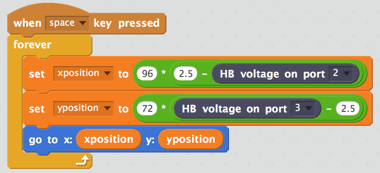
Once you can use the joystick to control a sprite, you can create whatever game you want. One example is given in JoystickGame.sb2 (see Teacher Materials). In this game, the joystick controls an octopus sprite. The horizontal and vertical positions of the joystick control the position of the sprite on the screen, and the button makes the octopus shoot bubbles. The goal of the game is to score points by avoiding the shark and shooting it with bubbles.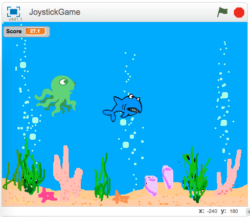
Controlling a Robot
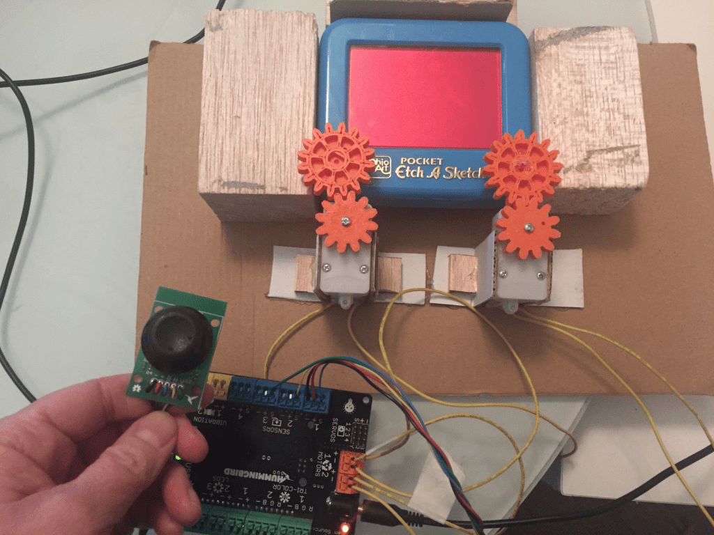
The joystick can also be used to control Hummingbird outputs, such as motors and LEDs. In this example, we chose to motorize an Etch-A-Sketch and control it with a joystick. Two motors were attached to the Hummingbird board. Each motor had a gear attached to it. These gears were couple to gears glued to the knobs on a small Etch-A-Sketch. If you want to try this, you can 3D print some gears using the 3D Printing and Hummingbird tutorial.
The script below was used to control the Etch-A-Sketch robot. This code looks very similar to the script used to control a sprite with the joystick. The main differences are the scaling factors used to convert the range of the joystick to an appropriate range of motor speed. In the script below, the scaling factors are both equal to 20. This script maps the 0 to 5 V range of the horizontal and vertical joystick sensors to a motor speed range of -50 to 50. What scaling factor would you use to get a motor speed range of -100 to 100?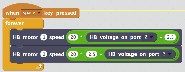
The joystick can also be used to control lights, sound, or servo motors. It can even be used with another sensor. We’d love to see what you try with it!