Register to receive free access to all teacher materials.

l Projects
Programming Language
Any language supported by Hummingbird Duo
Subjects
Math, Science
Grades
9-12
Free Teacher Materials
In this lesson, you will be building mechanisms with gears. Watch this video to see an example.
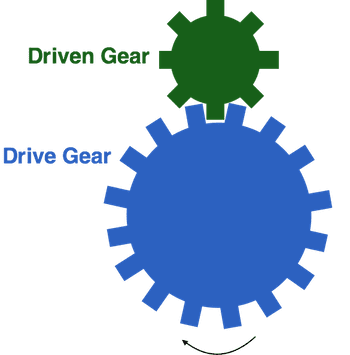
A gear train is a mechanism that consists of two or more gears. Gears are disks with teeth that mesh together. The diagram below shows a gear train with two gears. This mechanism has the following parts:
- The drive gear is rotated by a motor.
- The teeth of the drive gear mesh with those of the driven gear.
As the drive gear rotates, its teeth turn the driven gear. How fast the driven gear rotates depends on the number of teeth it has relative to the number of teeth of the drive gear.
Materials Needed
Paper Templates (See Teacher Materials)
When printing the templates, be sure to print them the actual size (no scaling) on 8.5” x 11” paper. You will use the templates to cut cardboard as shown in the instructions below. Be sure to use cardboard that is less than ⅛” thick.
- Motor Unit
- Box Unit
Other Materials
Building the Gear Train Mechanism
- Gear motor plus plastic brick adapter
- Pipe cleaner
- 3 Technic friction axle pegs
- 1 Technic 13M beam
- 2 Technic gears with 40 teeth
- 1 3M Technic axle
- 1 Technic bushing
Additional Materials for Investigating the Gear Ratio
- Pipe cleaner
- 1 Technic gear with 24 teeth
- 1 Technic gear with 8 teeth
- Stopwatch
Additional Materials for Extending the Gear Train
- More axles, bushings, and gears
Building the Gear Train Mechanism
- You will need a motor unit for this lesson. You may have already built one. If not, you can use these instructions to assemble the motor unit.
- Next, use this video to assemble your gear train mechanism.
- Attach the motor to motor port 1 on your Hummingbird board. Write a simple program to turn on the motor. Observe the movement of the gears.
- Does the drive gear rotate clockwise or counterclockwise? Does the driven gear rotate clockwise or counterclockwise?
Investigating the Gear Ratio
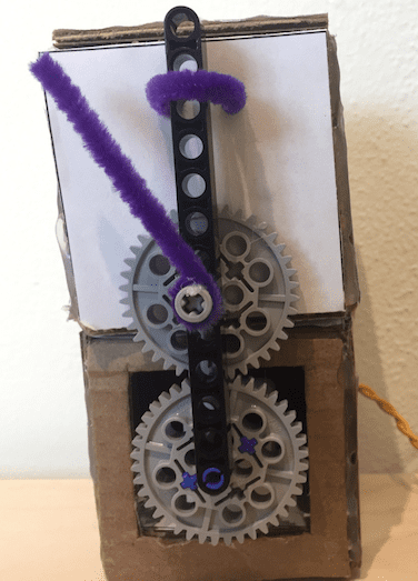
- Glue a small piece of pipe cleaner to the bushing, as shown in the picture below.
- Set the motor speed to 40 and measure the amount of time that it takes the driven gear to make ten rotations.
- Start the stopwatch when the pipe cleaner passes the black beam.
- Stop the stopwatch when the pipe cleaner has made ten complete rotations. The pipe cleaner should be in the same position that it was when you started the stopwatch.
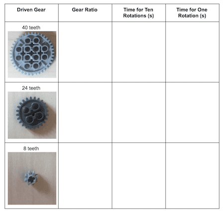
- Enter your measurement in the table below and compute the time required for one rotation of the driven gear.
- What is the time required for one rotation of the drive gear? Explain your answer.
- Replace the driven gear with a gear with 24 teeth. This video will show you how. Make sure that the teeth of the drive gear mesh with the teeth of the new driven gear.
- Set the motor speed to 40 and measure the amount of time that it takes the driven gear to make ten rotations.
- Enter your measurement in the table and compute the time required for one rotation of the driven gear.
- Replace the driven gear with a gear with eight teeth. Make sure that the teeth of the drive gear mesh with the teeth of the new driven gear.
- Set the motor speed to 40 and measure the amount of time that it takes the driven gear to make ten rotations.
- Enter your measurement in the table and compute the time required for one rotation of the driven gear.
- The gear ratio is defined as the proportion that relates the number of teeth on the driven gear to the number of teeth on the drive gear.

- Compute gear ratio for each driven gear and enter it in the table.
- Based on your data, write an equation that predicts the time for one rotation of the driven gear based on the gear ratio and the time for one rotation of the drive gear. You should be able to defend your equation.
Extending the Gear Train
A gear train can include more than two gears. Gears in between the drive gear and the driven gear are called passive gears. For example, the picture below shows a gear train with three gears. The 24-tooth gear in the middle is a passive gear.
Try building different gear trains. How does the number of gears in the train influence the direction of rotation of the driven gear?
In this lesson, the gear ratio was always greater than or equal to 1. However, this is not a requirement. Try using a smaller gear as the drive gear!
Using Gears to Create Robots
Gears are used in a robot design to increase or decrease the speed of a motor. Increasing the speed of the motor decreases the torque that it can apply; this means that the motor cannot apply as much force to rotate an object. Decreasing the rotation speed of the motor increases the amount of torque that it can apply. If you need your robot to rotate something heavy, you will need to use gears to decrease the rotation speed.
Gear trains are often used to in vehicles; for example, this video shows how gears are used in a car. However, gears can also be used in many other ways. The video below shows how gears were used to create a robotic Etch-A-Sketch and ballerinas that rotate at different speeds.
Now it is time to use gears to create your own robot! Do you want to increase or decrease the rotation speed of the motor? How many gears do you need in your gear train?
Finding More Information
- How to Determine Gear Ratio: Good explanation of calculating gear ratio.
- How a Watch Works: An interesting example of how a gear train is used in a mechanical watch.