Register to receive free access to all teacher materials.

l Projects
Programming Language
Any language supported by Hummingbird Duo
Subjects
Math, Science
Grades
9-12
Free Teacher Materials
In this lesson, you will be building a crank mechanism. Watch this video to see what it will look like.
This mechanism has three parts:
- The crank is attached to a motor that rotates it.
- The rod is attached to the crank using a connecting pin. The rod is free to rotate about this pin.
- The guide is fixed in place; its purpose is to keep the rod in place horizontally. The rod is free to rotate and move vertically.
As the crank rotates, the rod moves back and forth. This type of back and forth motion is called reciprocating motion.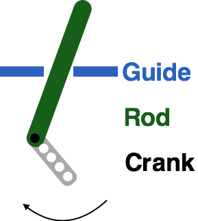
Materials Needed
Paper Templates (See Teacher Materials)
When printing the templates, be sure to print them the actual size (no scaling) on 8.5” x 11” paper. You will use the templates to cut cardboard as shown in the instructions below. Be sure to use cardboard that is less than ⅛” thick.
- Motor Unit
- Box Unit
Other Materials
- Gear motor plus plastic brick adapter
- 3 Technic friction axle pegs
- 2 Technic beams: 5M and 13M
- Pipe cleaner
- Cardboard
- Construction paper
- Pencil
Building the Crank Mechanism
- You will need a motor unit for this lesson. You may have already built one. If not, you can use these instructions to assemble the motor unit.
- Next, use this video to assemble your crank mechanism.
- Attach the motor to motor port 1 on your Hummingbird board. Write a simple program to turn on the motor. Observe the movement of the crank and the rod.
- Change the speed of the motor. How does this change the movement of the rod?
Calculating How Far the Crank Moves
You can use geometry to calculate how far the crank will move horizontally and vertically.
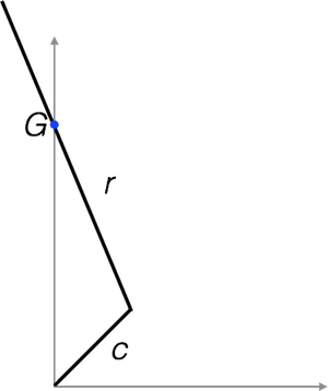
- This diagram shows an idealized version of the crank mechanism. The length of the crank is c, and r is the length of the rod. G is the point where the guide keeps the rod in place. The rod must always pass through this point.
- Draw the crank and guide when the rod is at its highest point. What are the coordinates of the top of the rod in terms of c and r?
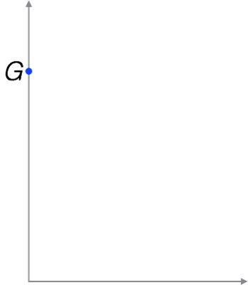
- Draw the crank and guide when the rod is at its lowest point. What are the coordinates of the top of the rod in terms of c and r?
- In terms of c and r, what is the vertical distance that the top of the rod moves between its highest and lowest points?
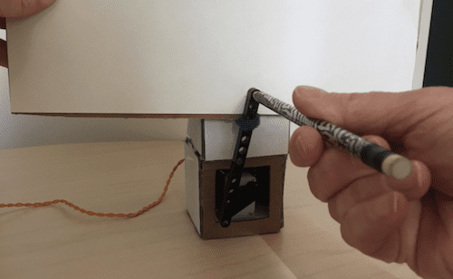
- Measure c and r for your crank mechanism. The length of the rod should be measured from the center of the connecting pin to the center of the hole at the end of the rod. The length of the crank should be measured from the center of the motor to the center of the connecting pin at the end of the crank, as shown in the picture below.

- Use your measurements to calculate the vertical distance that the rod moves.
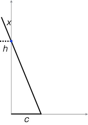
- Next, you will find the horizontal distance that the rod moves as it travels. The crank mechanism is shown below with the crank lying along the x-axis. The distance h is the maximum distance that the top of the rod moves to the left of the y-axis.
- What similar triangles can you find in the diagram above? Use the properties of similar triangles to fill in the blanks in the equation below.

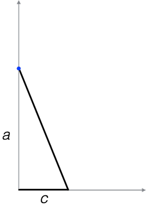
- Consider the triangle below point G. We will call the height of this triangle a. Measure the value of a for your crank mechanism by measuring the vertical distance from the center of the motor to the guide.
- Now that you have values for a and c, find the length of the third side of the triangle in the diagram above.
- Now you have enough information to find h! Use your equation from (8) to solve for h. What is the total horizontal distance that the end of the rod moves?
Finding the Path of the Rod
Next, you will trace the path of the end of the rod. This way, you can get a better idea of the type of movement caused by a crank. This process is shown in this video and described below.
- Tape a piece of paper onto a piece of cardboard about the same size. Place this behind the end of the rod.
- Place a pencil through the top hole of the rod.
- As the rod moves, use the pencil to trace its path. Try not to affect the motion of the rod; just follow it with the pencil.
- Remove the paper and the pencil. Darken the path you traced and measure its maximum width and height.
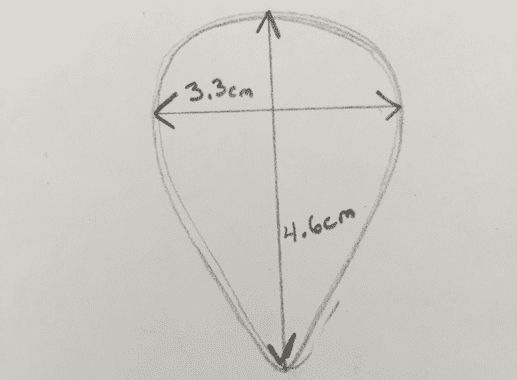
- How do these values compare with the ones that you calculated above?
Changing the Length of the Crank
Now you will investigate how you can change the motion of the mechanism by changing the length of the crank. You can change the length of the crank by using the other two holes along the length of the crank.
- Use this video to change the length of the crank. Move the connecting pin to the next hole on the crank.
- Trace the path of the rod. Measure the maximum width and height of the new path.
- Change the length of the crank again. This time, place the connecting pin between the two pins that connect the crank to the motor adapter.
- Trace the path of the rod. Measure the maximum width and height of the new path.
- How does changing the length of the crank affect the path of the rod?
Using Cranks to Create Robots
Cranks can be incorporated into a robot design in many different ways. Two examples are shown in this video. Can you identify the parts of the mechanisms in this video? In the fish example, how has the crank mechanism been modified?
Now it is time to use a crank to create your own robot! How can you use reciprocating motion to make make something interesting? Do you need to modify the crank, rod, or guide for your design?
Finding More Information
- Crank: This website animates the movement of a crank mechanism and describes its parts.
- Karakuri: How to Make Mechanical Paper Models that Move by Keisuke Saka: This book describes a number of mechanisms. It comes with paper models of different mechanisms and examples of how they can be used in fun ways.