Register to receive free access to all teacher materials.

l Projects
Programming Language
Any language supported by Hummingbird Duo
Subjects
Math
Grades
9-12
Free Teacher Materials
Standards
This lesson is aligned with Common Core math standards that focus on creating and solving equations (A-CED, A-REI-A, and A-REI-B). It also meets geometry standards on congruence (G-CO-B) and the use of geometry in modeling (G-MG).
In the last two lessons, you learned to make mechanisms with cranks, rods, and pistons. These mechanisms are special cases of a more general type of mechanism called a linkage. In this lesson, you will explore other types of linkages. Watch this video for an example.
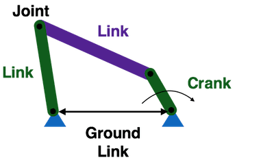
The diagram below shows a four-bar linkage. This mechanism has the following parts:
- Four links that are connected by four rotating joints.
- Three of the links can move, but the fourth is fixed in position. This link is called the ground link.
- One of the moving links is a crank that is rotated by a motor.
As the crank rotates, it causes two other links to move while the ground link remains fixed in position. Varying the lengths of the links produces different patterns of movement.
Materials Needed
Building the Four-Bar Linkage Mechanism
- motor unit with gear motor plus plastic brick adapter
- pipe cleaner
- 5 Technic friction axle pegs
- Laser Cut Motor & Linkage Unit (see Teacher Materials)
Additional Materials for Exploring More Complex Linkages
- 7 Technic friction pegs
- motor unit with gear motor and plastic brick adapter
- small box
- pipe cleaner
- marker
Building the Four-Bar Linkage Mechanism
- You should complete the crank lesson prior to this one. If you have not already completed the crank lesson, do that first. This lesson will use the motor unit from the crank lesson.
- Next, use this video to assemble your linkage mechanism.
- Attach the motor to motor port 1 on your Hummingbird board. Write a simple program to turn on the motor. Observe the movement of the four-bar linkage.
Grashof Condition
Not every set of link lengths will produce a working four-bar linkage. The lengths must satisfy an equation known as the Grashof condition. This equation is defined in terms of the following variables:
- s is the length of the shortest link
- l is the length of the longest link
- p is the length of one of the intermediate links
- q is the length of the other intermediate link

- Measure the lengths of all four of the links in your mechanism (including the ground link). Which links are s and l?
- You have seen that your linkage can move, so you know that it should satisfy the Grashof condition. Use your measurements to show that it does.
- Next, move the pin that connects the two long links. Place this pin so that it is in the center hole for both of these links. You may have to rotate the crank to reconnect the two links.
- How have the link lengths changed for your mechanism? Does the linkage still meet the Grashof condition? Predict whether or not the linkage will be able to move.
- Turn on the motor. Can the linkage move? Does this support or contradict your prediction?
- Again, move the pin that connects the two long links. Place this pin so that it is in at the end of one link and the middle of the other. You may have to rotate the crank to reconnect the two links.
- How have the link lengths changed for your mechanism? Does the linkage still meet the Grashof condition? Predict whether or not the linkage will be able to move.
- Turn on the motor. Can the linkage move? Does this support or contradict your prediction?
Building a Scisssor Linkage
- Use this video to transform your four-bar linkage into a scissor linkage. You will need six more connecting pins and the cardboard parts that you set aside earlier.
- This mechanism is based on a four-bar linkage, but it uses additional links to increase the amount of movement produced by the linkage.
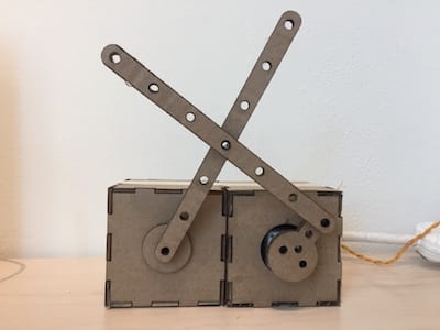
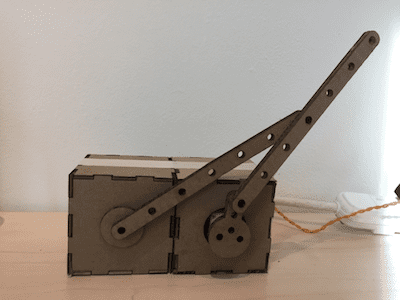
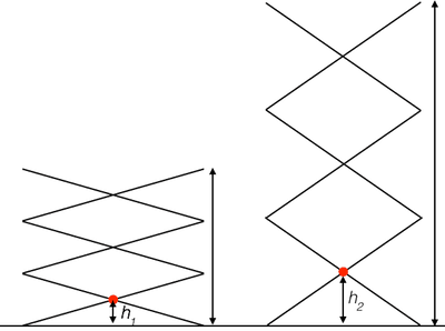
- The picture below shows a scissor linkage at two different positions.
- As the red point on the linkage moves from height h1 to height h2, how far does the top of the linkage move? Defend your answer using congruent triangles.
- Based on your answer, what is the advantage of a scissor linkage? Can you think of any disadvantages?
- We used a scissor linkage to animate a fish leaping out of the water. What are some other ways that you might use a scissor linkage in a robot?

Exploring More Complex Linkages
- For the next part of this lesson, you will need two motor units. You can use these instructions to assemble one, or you can team up with a neighbor!
- Use the two motor units to create a new linkage for drawing. You will need a small box, a pipe cleaner, paper, a marker, and 7 connecting pins.
- Attach the motors to motor ports 1 and 2 on your Hummingbird board. Write a program to turn on the motors. What does your robot draw?
- Vary the speeds of the motor. Use a different piece of paper for each speed combination and label it with the speeds you used. This will enable you to compare your drawings more easily.
- How do the speeds of the two motors affect what your robot draws?
- What does the robot draw when the two speeds are equal? How is this different from the drawings when the speeds are different?
- Your drawing robot is a five-bar linkage. Draw a picture of it and label the five links (don’t forget the ground link!).
- A five-bar linkage can move in more different ways than a four-bar linkage. That is why you can use two cranks to make two of the links rotate independently. What would happen if you tried to attach motors to two of the links in a four-bar linkage?
Using Linkages to Create Robots
In this lesson, you have used different kinds of linkages to create several different robots, but there are so many more possibilities! Theo Jansen even uses linkages to create enormous works of art!
As examples, this video shows a linkage that was used to make the wings of a penguin flap, and the video below shows a robot arm that incorporates a number of linkages. How would you describe the linkages shown in these videos?
Now it is time to use linkages to create your own robot! How can you modify the linkages you used in this lesson to make something new?
Finding More Information
- Linkage Experiments: The Tinkering Studio has a lot of creative ideas for using linkages!
- Mechanical Invention through Computation: Mechanism Basics: These slides describe many different types of linkages and show some historical examples.