Register to receive free access to all teacher materials.

l Projects
Programming Language
Any language supported by Hummingbird Duo
Subjects
Math
Grades
9-12
Free Teacher Materials
Standards
This lesson is aligned with Common Core math standards that focus on creating and interpreting scatter plots of data (S-ID-B).
In this lesson, you will be extending your crank mechanism to create a crank and piston mechanism. Watch this video to see what it will look like.
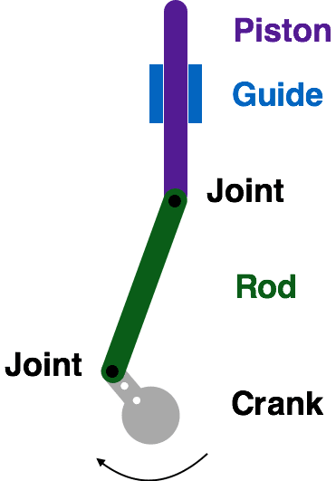
This mechanism has four parts:
- The crank is attached to a motor that rotates it.
- The rod is attached to the crank and the piston at joints that are free to rotate.
- The guide is fixed in place; its purpose is to make the piston move in a line. The piston is free to move up and down in a line but cannot rotate.
As the crank rotates, the piston moves up and down in a linear reciprocating motion. A crank and piston system transforms rotational motion into linear motion. The linear motion can be vertical or horizontal (or in another direction), depending upon the orientation of the guide.
Materials Needed
- crank mechanism (from crank lesson)
- 1 Technic friction axle peg
- ruler or tape measure
- stopwatch
- Laser Cut Piston Unit (see Teacher Materials)
Building the Crank and Piston Mechanism
- You will need a crank mechanism for this lesson. If you have not already completed the crank lesson, do that first.
- Next, use this video to assemble your crank and piston mechanism.
- Attach the motor to motor port 1 on your Hummingbird board. Write a simple program to turn on the motor. Observe the movement of the mechanism.
Graphing the Position of the Piston
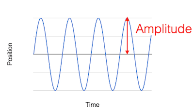
Think about starting a timer when you turn on the motor. As the seconds pass, the crank rotates and the piston moves up and down. We could make a graph with time on the x-axis and the position of the piston on the y-axis. This graph would look something like the curve shown below.
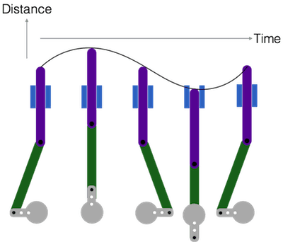
The figure above shows only a single rotation of the crank. As the crank rotates again and again, this curve would be repeated. This type of periodic motion is called a wave.
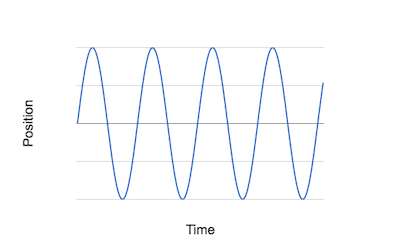
- The highest point of a wave is called the peak, and the lowest point is called the trough. Label one peak and one trough on the graph above.
- The distance between the peak and the trough is called the wave height. Label the wave height on the graph above.
- How can you find the wave height for the piston? Measure this value and then compare your method and answer with your classmates.
- A wave is often described by its amplitude instead of its wave height. The amplitude is half of the wave height. Find the amplitude of the piston wave.
Changing the Length of the Crank
Now you will investigate how you can change the piston wave by changing the length of the crank. You can change the length of the crank by using the other holes along the length of the crank.
- Move the connecting pin at the end of the crank to the neighboring hole.
- Measure the amplitude of the piston wave.
- Change the length of the crank again. This time, place the connecting pin in the hole closest to the two connecting pins that connect the crank to the motor adapter.
- Measure the amplitude of the piston wave.
- How is the amplitude of the piston wave related to the length of the crank?
- Can the rod ever be shorter than the crank? Why or why not?
Period of the Piston Wave
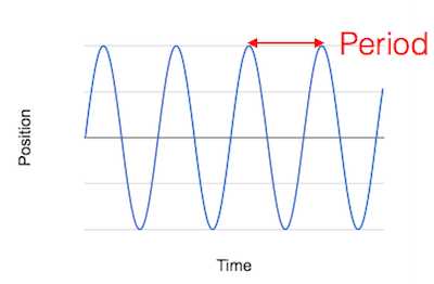
The time period between one peak and the next is called the period of a wave.
- Set the speed of the motor to 20.
- Use a stopwatch to measure how long it take the crank to rotate 10 times.
- What is the period of the wave?
- Complete the table below.
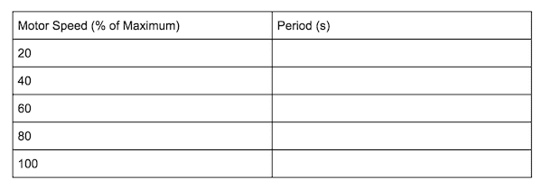
- How is the period of the wave related to the speed of the motor? Predict the period for a speed of 50 and give evidence for your answer.
- Check your answer for the previous question. How close was your prediction?
Using Cranks and Pistons to Create Robots
Crank and piston mechanisms are used in robots to produce linear movement in a particular direction. For example, this video shows a project in which a piston is used to move a character up and down. Can you identify the parts of the mechanism in the video? This robotic turtle also uses a crank and piston. What might be inside the turtle’s shell?
Now try it out in your own robot! How far do you want to move the piston? How long do the crank and connecting rod need to be to make this happen? Remember, the piston does not have to move only vertically or horizontally. It can move along a straight line in any direction!
Finding More Information
- Crank and Slider Mechanism: This website animates the movement of a crank and piston mechanism and describes its parts.
- Diesel Engine: This video shows how a diesel engine uses a crank and piston mechanism in a car or truck. In this case, the explosion of the fuel produces the linear motion of the piston, and the mechanism transforms this motion to rotate the wheels of the vehicle.