Register to receive free access to all teacher materials.

l Projects
Programming Language
Any language supported by Hummingbird Duo
Subjects
Math
Grades
9-12
Free Teacher Materials
In this lesson, you will be building a cam mechanism. Watch this video to see what it will look like. The rotating disk makes the post move up and down.
This mechanism has three main parts:
- A cam is a flat disk that is rotated by a motor.
- The cam follower sits on top of the cam. It moves up and down as the cam rotates.
- The guide is fixed in place; its purpose is to keep the cam follower positioned above the cam.
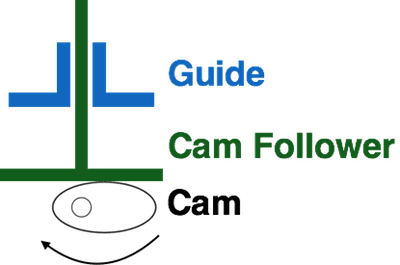
The cam follower moves loosely in the guide. The cam pushes the follower up, and gravity pulls it down. This means that a cam mechanism transforms rotation into vertical motion.
Materials Needed
- Gear motor plus plastic brick adapter
- 2 Technic friction axle pegs
- ¼” dowel rod approximately 6” long
- 2 pennies
- Craft stick (popsicle stick)
- Rubber band
- Laser Cut Cam & Motor Unit (see Teacher Materials)
Building the Cam Mechanism
- You will need a motor unit for this lesson. You may have already built one. If not, you can use these instructions to assemble the motor unit kit.
- Next, use this video to assemble the parts in your cam mechanism kit. There are a lot of parts, so take your time and be sure to follow the directions carefully.
- Attach the motor to motor port 1 on your Hummingbird board. Write a simple program to turn on the motor. Observe the movement of the cam and cam follower. Important Note: You will need to hold the motor unit and cam assembly in place.
- Change the speed of the motor. How does this change the movement of the cam follower?
Drawing Your Observations
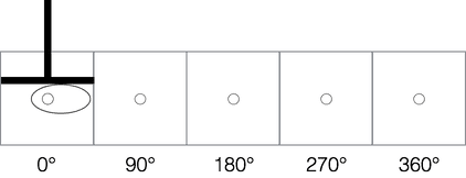
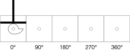
The first entry in the table below shows the cam pointing to the right and the cam follower on top of it. Imagine that the cam rotates clockwise.
- Where will it be after it rotates 90°? Draw that position in the table.
- Draw the position of the cam after it rotates 180°, 270°, and 360°.
- For each angle, draw the position of the cam follower.
- At what angle will the follower be at its highest point?
- At approximately what angle will the follower be at its lowest point?
- How can you find the distance that the cam follower travels between its highest and lower points?
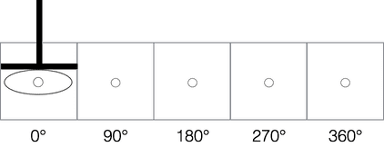
Second Oval Cam
Consider the second oval cam, which is shown in the table below. Imagine that the cam rotates clockwise. Draw the position of the cam for each angle in the table below, and then draw the position of the cam follower.
- At what angle will the follower be at its highest point?
- At approximately what angle will the follower be at its lowest point?
- What distance does the cam follower travel between its highest and lower points?
- Watch this video to learn how to remove a cam and change it for a different one. Put the second oval cam on the dowel rod. Turn on the motor and observe the movement of the cam mechanism.
- Does its movement match your predictions? How does the movement differ from what you observed with the first cam?
- Make the motor speed negative to turn the cam in the opposite direction. How does this affect the movement of the cam follower?
- At what position(s) of the cam does the cam follower move most quickly? Where does it move slowly?
Snail Cam
Complete the table below for the third cam, which is called a snail cam. For the table, assume that the cam rotates clockwise.
- What do you think will happen when the cam rotates counterclockwise? After you complete the table, test your predictions.
Heart Cam
The last cam is the heart cam. Consider its shape.
- When will the cam follower be at its highest point?
- When will the cam follower be at its lowest point?
- At what position(s) of the cam will the cam follower move most quickly? Where will it move slowly?
- Test your predictions. Is there anything you did not expect about how this cam moves?
Using Cams to Create Robots
This video shows just two of the many possible ways that you might use cam mechanisms to make robots. Can you identify the parts of the mechanisms in this video?
Now that you have explored how cams work, you are ready to use them in your own creation! Design a robot that uses at least one cam. Maybe you even want to include multiple cams or design your own cam shape!
Finding More Information
- Cam Mechanisms: This website animates the movements that results from different cam shapes.
- Cams and Followers: You used a cam follower with a flat bottom in this lesson, but you can learn about other choices for the cam follower here.
- Karakuri: How to Make Mechanical Paper Models that Move by Keisuke Saka: This book describes a number of mechanisms. It comes with paper models of different mechanisms and examples of how they can be used in fun ways.