Register to receive free access to all teacher materials.

l Projects
Programming Language
Any language supported by Hummingbird Duo
Subjects
Math
Grades
9-12
Free Teacher Materials
Standards
This lesson is aligned with Common Core math standards that focus on geometric construction (G-CO-D) and the use of geometry in modeling (G-MG). It can be modified to use trigonometry (G-SRT-C) instead of geometric construction.
In this lesson, you will be building a cable-driven robot. Watch this video to see what it will look like.
The mechanism includes the following parts:
- Links are connected by rotating joints.
- A hollow guide is attached to each link.
- A cable passes through all the guides. This cable is attached to a motor.
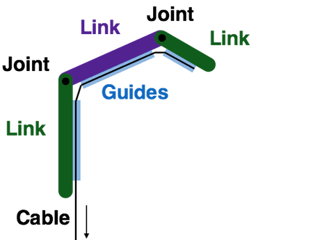
The motor pulls on the cable to move the links. As the motor pulls the cable, the guides become closer together, which makes the links rotate about the joints. Note that the cable can only move the mechanism in one direction, to bend the linkage at the joints.
Materials Needed:
- servo motor with bag of accessories
- straws cut into 2” pieces (12 pieces)
- yarn or cord
- optional: Tapestry needle
- Laser Cut Servo & Cable Driven Unit (see Teacher Materials)
Building a Cable-Driven Robot
- Use this video to assemble the servo motor unit.
- Attach the servo motor to your Hummingbird board and set it to 0°.
- Next, assemble the cable-driven mechanism using the video below. You may find it helpful to use a tapestry needle to thread the cable through the straws.
- Reattach the servo to the Hummingbird board. Gradually increase the angle of the servo and observe the movement of the links.
- Continue to increase the servo angle until the links stop moving. This is the maximum angle that you should use with your mechanism. Record this angle.
- Write a program to move the servo back and forth between 0° and the maximum angle.
- The motor acts to bend the linkage. What provides the energy to straighten the linkage? How could you use another servo to straighten the linkage?
- We used a cable-driven mechanism to create this giraffe. What are some other ways that you might use this mechanism in a robot?
How the Mechanism Operates
You can use geometry to investigate how moving the cable causes the cable-driven linkage to bend at the joints.
- The diagram below shows one joint of the cable-driven robot. We can approximate this as the triangle JAB. Assuming that the joint is midway between the two guides, what type of triangle is JAB?
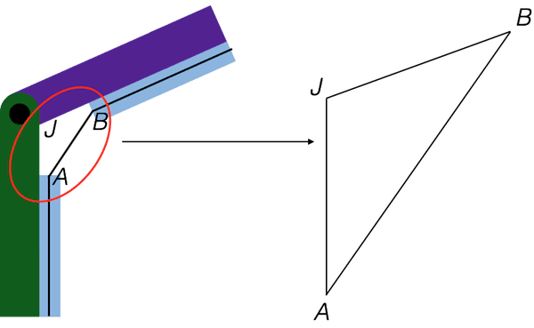
- Use your mechanism to measure the length of line segments JA and JB. Do these measurements support your answer to (1)? Explain.
- Angle AJB in the diagram measures 110°. Draw a scaled version of triangle JAB using the measurements that you have taken so far and this angle. Lengths in the scaled version should be 10 times larger than the real-world lengths.
- Measure the scaled length of line segment AB. What real-world length does this correspond to?
- When the motor pulls on the cable, it acts to shorten the line segment AB. Suppose that the length of AB decreases by 20%. What is the new scaled length of this line segment?
- Construct a new scaled version of triangle JAB using the decreased length. Measure angle AJB.
- How has the change in cable length affected angle AJB? Explain what this means for a cable-driven robot.
Using Two Linkages
You can create a cable-driven robot with multiple linkages. In this part of the lesson, you will connect two linkages to your servo motor unit. Examples with even more linkages are shown below.
- Make sure your servo motor is set to 0°.
- Use this video to modify your cable-driven mechanism to include two linkages. You will need a second cardboard box as a spacer. You may have one from a previous lesson, or you can make a second box using the instructions and laser cutter file above. Alternatively, you can team up with a neighbor for this section!
- Reattach the servo to the Hummingbird board. Gradually increase the angle of the servo and observe the movement of the links.
- Continue to increase the servo angle until the links stop moving. This is the maximum angle that you should use with your mechanism. Record this angle.
- Write a program to move the servo back and forth between 0° and the maximum angle.
- Compare your two-linkage mechanism to the version with a single linkage. Do the two linkages move symmetrically? Why or why not?
- We used two cable-driven linkages to create this bird. What are some other ways that you might use this mechanism in a robot?
Creating Cable-Driven Robots
You have already seen the giraffe and bird examples, but the you can create many other cable-driven robots! This video shows a cable-driven robotic hand.
In this lesson, the linkages were created from cardboard, but you can use other materials. This blooming flower was created with stiffened felt.

Now it is time to create your own cable-driven robot! How many linkages will you need? Will you connect them to the same servo or to different servos?
Finding More Information
- CableRobot-Simulator: Prototype robot that uses many cables and winches to move the user around a large space.
- Making a Robot Hand with Hummingbird: Tutorial to construct the robot hand shown in the video above.